How to Measure Roll Diameter Using a Laser Distance Sensor
In paper converting, plastic film production, printing, and textile manufacturing, roll diameter directly affects machine speed, web tension, and material handling. A laser distance sensor for roll diameter measurement allows engineers to monitor roll growth or reduction continuously without touching the moving material. This makes it useful for both winding and unwinding applications where reliable diameter feedback is required.
Unlike manual inspection, a laser-based system can supply real-time distance data to a PLC or industrial controller. However, accurate results depend on the sensor’s measurement range, mounting geometry, surface conditions, and calculation method. Choosing a suitable sensor is only the first step; the complete measurement system must also be configured and validated correctly.
This guide explains how a laser distance sensor for roll diameter measurement works, how to calculate diameter from distance readings, and how to improve measurement reliability in industrial production.
1. Why Is Roll Diameter Measurement Important?
During winding, material accumulates around a core and increases the roll diameter. During unwinding, the diameter decreases as material is consumed. If the control system does not know the current roll size, maintaining consistent production conditions becomes more difficult.
A laser distance sensor for roll diameter measurement provides a non-contact method of tracking these changes throughout the production cycle. The measured data can support several practical functions.
Winding speed compensation: As the roll grows, the rotational speed required to maintain a target web speed changes. A controller can use the calculated diameter to adjust the drive command.
Unwinding management: As the roll becomes smaller, diameter information helps the machine estimate remaining material and prepare for roll replacement.
Tension control: Diameter feedback can support a control strategy designed to maintain suitable web tension as the roll changes size.
Production monitoring: Unexpected diameter changes may indicate uneven winding, material buildup, or a measurement problem that requires inspection.
A laser distance sensor for roll diameter measurement does not replace the machine controller. Instead, it supplies measurement data that the controller uses alongside rotational speed, tension, and other process variables.
2. How Does a Laser Sensor Measure Roll Diameter?
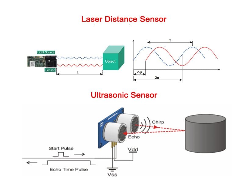
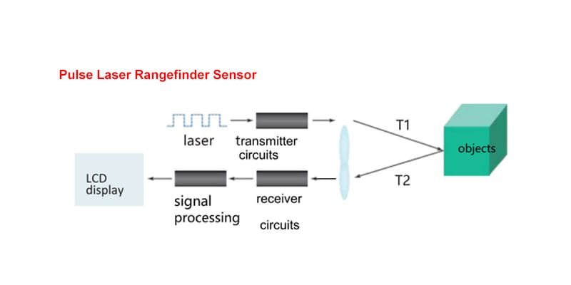
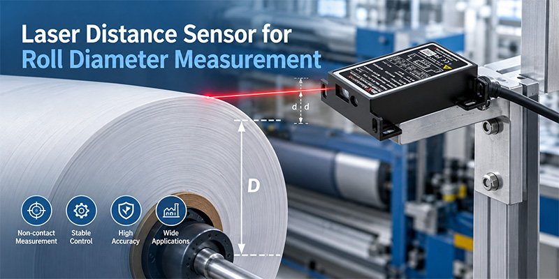
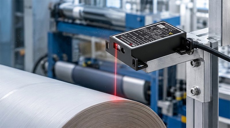
A laser distance sensor measures the distance between its measurement reference and the surface of a target. When the sensor is fixed above a winding roll, the measured distance changes as the outer diameter increases or decreases.
For example, when additional film is wound onto the core, the top surface moves closer to the sensor. The measured distance becomes shorter. When material is unwound, the surface moves farther away and the measured distance increases.
The relationship between distance and diameter depends on the installation geometry. In a common arrangement, the sensor points vertically toward the top of the roll and is aligned with the roll centerline.
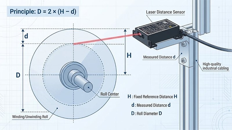
The diagram should label the fixed sensor-to-center distance as H, the measured distance to the roll surface as d, and the roll diameter as D. It should also show small and large roll outlines to explain how the measured distance changes.
A laser distance sensor for roll diameter measurement must use a known geometric reference to convert distance into diameter. Without that reference, the sensor provides a surface distance rather than the actual roll diameter.
3. How to Calculate Roll Diameter from Distance Readings
For a sensor mounted directly above the roll center, the diameter can be calculated using the following equation:
D = 2 × (H − d)
Where:
- D = roll diameter
- H = fixed vertical distance from the sensor reference to the roll center
- d = measured distance from the sensor to the top surface of the roll
Consider a practical example. The fixed distance H is 800 mm, and the sensor measures a surface distance d of 500 mm.
D = 2 × (800 − 500) = 600 mm
The calculated roll diameter is therefore 600 mm.
If the roll grows and the measured distance decreases to 400 mm, the calculated diameter becomes:
D = 2 × (800 − 400) = 800 mm
This calculation assumes that the sensor remains fixed, the beam points toward the top surface, and the installation geometry matches the stated reference. A side-mounted sensor or a sensor aimed at another part of the roll requires a different geometric calculation.
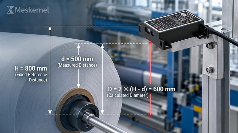
When configuring a laser distance sensor for roll diameter measurement, engineers should also define acceptable minimum and maximum diameter values. Readings outside the expected range may indicate an incorrect reference, an obstructed beam, an empty core, or a sensor signal problem.
4. How to Install the Sensor for Reliable Results
Correct installation is essential for a reliable laser sensor for roll diameter measurement. Before mounting the device, confirm the minimum and maximum roll diameters, available mounting space, required response time, and expected operating environment.
Choose a stable mounting position. Attach the sensor to a rigid bracket that does not move with the machine frame or roll assembly. Bracket vibration can introduce apparent distance changes that are unrelated to the actual roll diameter.
Keep the optical path clear. Aim the laser at the roll surface rather than the shaft, flange, or surrounding machine components. Check the complete operating range to ensure that no component blocks the beam as the roll grows.
Verify the measurement range. The sensor must cover the full distance variation between the smallest and largest roll sizes. Include suitable allowance for mounting tolerances and normal mechanical movement.
Test the actual material. Dark films, glossy plastic, metallic foil, paper, and textiles can produce different optical responses. Verify signal stability using the material and surface finish that will be used in production.
Protect the sensor. Paper dust, fibers, and adhesive residue can affect the optical window. Depending on the environment, an appropriate protective housing or air purge may help maintain stable operation.
For additional installation guidance, see our How to Install a Laser Distance Sensor Correctly guide. Replace the placeholder with the actual URL of your existing installation article before publishing.
5. What Factors Affect Measurement Accuracy?
The accuracy of a laser distance sensor for roll diameter measurement depends on both sensor performance and the mechanical conditions of the application.
Sensor accuracy and repeatability: Accuracy describes how closely a result approaches the actual value, while repeatability describes the consistency of repeated measurements under comparable conditions. Both should be evaluated against the application’s requirements.
Roll runout and eccentricity: A roll may not be perfectly circular or may rotate slightly off-center. Consequently, the sensor reading can fluctuate during rotation even when the overall roll size has not changed significantly.
Surface reflectivity: Optical performance can vary with material color, gloss, texture, and reflectivity. A sensor that works well on white paper may behave differently on dark film or reflective foil. Testing on the real target is therefore important.
Mounting rigidity: Movement of the sensor bracket can be interpreted as movement of the roll surface. A stable mounting structure helps distinguish genuine diameter changes from mechanical vibration.
Sampling and filtering: Filtering can reduce short-term fluctuations caused by runout or surface irregularities. However, excessive filtering introduces delay and may prevent the controller from responding quickly enough to actual changes.
The diameter calculation also amplifies distance measurement error. Because D = 2 × (H − d), a 1 mm error in the measured distance produces approximately a 2 mm diameter error when H is fixed and the geometry is ideal. Uncertainty in the reference distance adds further error.
For demanding non-contact roll diameter measurement applications, the complete system should be tested at several known roll sizes rather than checked at only one diameter.
6. Connecting the Sensor to a Winding Control System
A typical automated system sends distance data from the sensor to a PLC or another industrial controller. Depending on the selected model, the connection may use an analog output or a supported digital communication interface.
The controller then converts the measured distance into diameter, checks the value against configured limits, and provides the result to the machine’s control logic.
A practical integration sequence includes:
- Read the sensor output.
- Check signal validity and detect measurement faults.
- Calculate roll diameter using the configured reference geometry.
- Apply appropriate filtering and plausibility checks.
- Send the calculated diameter to the winding or unwinding controller.
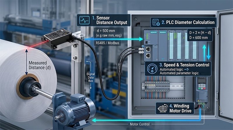
For a laser distance sensor for winding diameter control, response time and output compatibility are particularly important. The sensor must deliver usable measurements at the rate required by the machine, and the PLC must process the values without introducing excessive delay.
Diameter feedback can support speed compensation, roll-change preparation, and tension-control strategies. However, the control algorithm must account for other operating variables, including line speed, acceleration, material properties, and drive characteristics.
If your application requires short-range displacement monitoring in addition to roll diameter measurement, explore our Laser Displacement Sensor product category to compare suitable measurement solutions. Replace the placeholder with the real category URL on your website.
7. How to Select the Right Laser Distance Sensor
Choosing a sensor based only on its nominal accuracy can lead to problems during commissioning. Engineers should evaluate the entire application before making a selection.
Start by identifying the minimum and maximum roll diameters and the available sensor mounting distance. These values establish the required measurement range. Next, determine the acceptable diameter error, expected roll speed, and response time needed by the control system.
The target material should also be specified. Surface reflectivity and texture can influence measurement stability, while dust, temperature, and vibration can affect long-term operation.
Before confirming a laser distance sensor for roll diameter measurement, review these requirements:
- Full measurement range and installation distance
- Accuracy, repeatability, and resolution
- Response time and output interface
- Material type and surface reflectivity
- Roll runout and expected machine vibration
- Environmental protection requirements
- PLC compatibility and commissioning procedure
Where possible, test the proposed sensor on the actual machine or a representative test setup. Compare the calculated diameter against a trusted reference at multiple roll sizes, then evaluate stability while the roll is rotating.
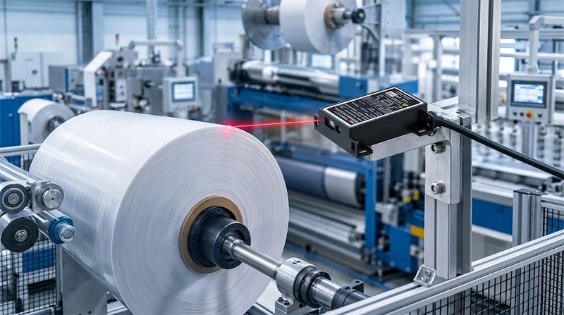
A properly configured laser distance sensor for roll diameter measurement can provide continuous, non-contact feedback for industrial winding and unwinding systems. Reliable performance comes from combining an appropriate sensor, stable mounting, correct geometry, and a control system designed for the application.
Frequently Asked Questions
Can a laser distance sensor measure roll diameter without contact?
Yes. The sensor measures the distance to the roll surface without physically touching the material. A controller calculates the diameter from the distance reading and the known installation geometry.
How is roll diameter calculated from laser distance?
For a sensor mounted directly above the roll center, the equation is D = 2 × (H − d). H is the fixed distance from the sensor reference to the roll center, and d is the measured distance to the top surface.
Which materials can be used for non-contact roll diameter measurement?
Paper, plastic film, foil, textiles, and other roll materials may be suitable. Actual performance depends on surface reflectivity, texture, measurement distance, and sensor design, so the target material should be tested before installation.
Can a laser distance sensor support automatic winding control?
Yes. When connected to a compatible PLC or controller, the sensor’s calculated diameter can support winding speed compensation, unwinding management, and roll-change planning. The final control strategy depends on the machine design.
How can engineers improve roll diameter measurement accuracy?
Use a stable mounting bracket, verify the geometric reference, select a suitable measurement range, test the actual target material, and account for roll runout. Validate the complete system against known roll diameters under representative operating conditions.